01
Basics, covered
12 / 24 / 48 V universal. P-type and N-type alternators. Three-stage charging (bulk / absorption / optional float) with intelligent tail-current detection and re-bulk logic. Third-party BMS integration.
12 / 24 / 48 V universal. P-type and N-type alternators. Three-stage charging (bulk / absorption / optional float) with intelligent tail-current detection and re-bulk logic. Third-party BMS integration.
$390 launch / $590 MSRP. Far less capable options land north of $700–$1,200.
Schematics, source code, design documentation. No black boxes, no secrets.
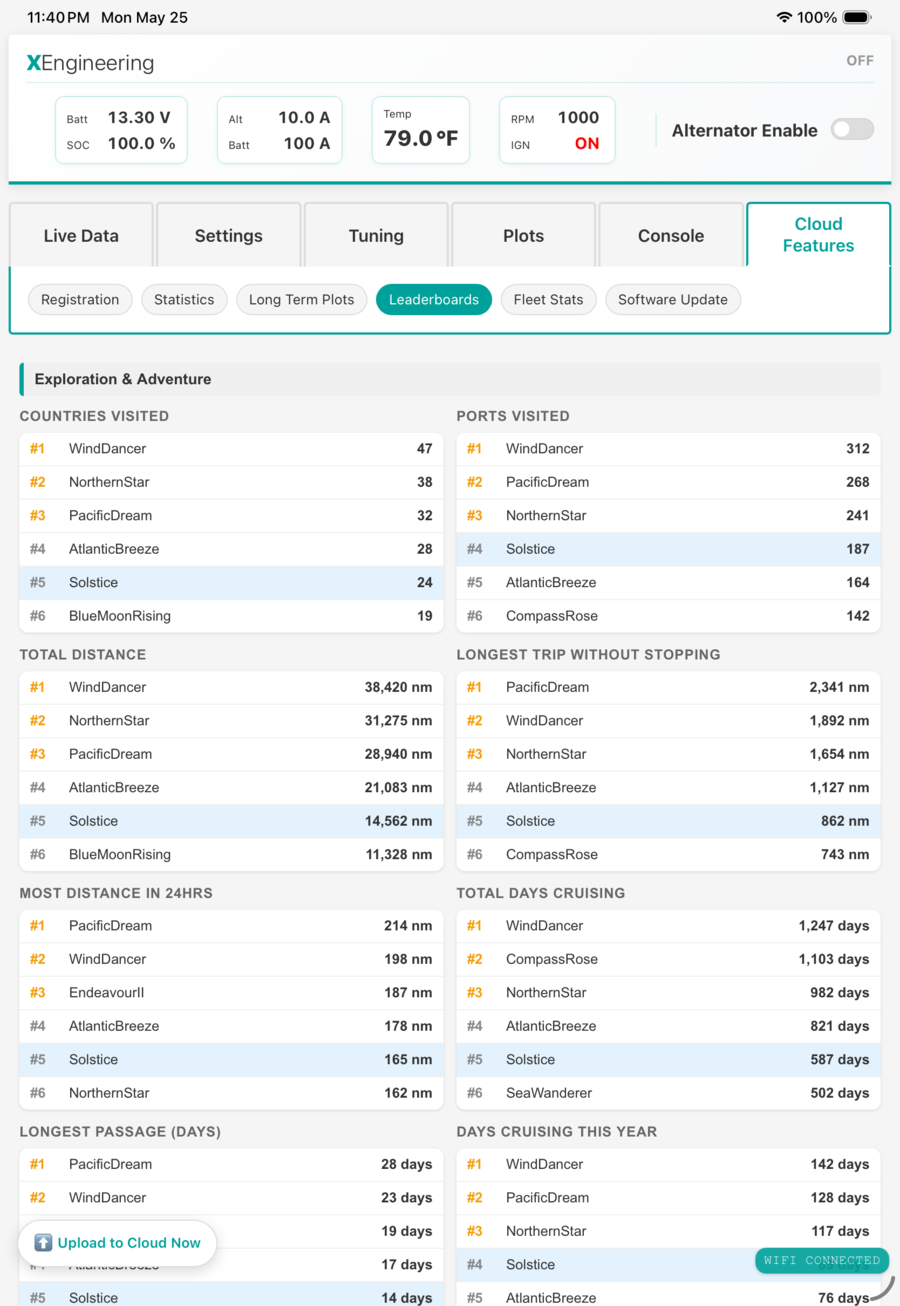
Your phone, tablet, or laptop dashboard streams 34 control-loop values at 10 Hz, plus >400 diagnostic values every 5 seconds.
80 hours of high-resolution data stored locally; infinite cloud history on top. Long-trend plots across years of cruising.
Global leaderboards for distance, days at sea, alternator and solar output, speed by boat type, and much more. Public fleet stats page.
Three cascaded PID loops with position-form PI, anti-windup, slope-aware integrator bleed, predictive rate-of-rise overvoltage protection, and bumpless transfer on every mode change. Smooth charging that won't spike, oscillate, or hunt.
Multi-layer thermal, voltage, and current protections. Redundant hardware safety that cuts output even if the firmware fails. Battery load-dump detection, sensor cross-validation, and staleness detection. Conformal-coated, EMI-hardened, reverse-polarity-protected hardware built for the marine environment.
Learns the alternator's output for a given RPM, field, battery voltage, and temperature — then flags when performance deteriorates. A physics-based life model predicts time-to-failure. How it works →
Tracks boat speed and comfort against wind and sea conditions — compare live data to your best polars to optimize sail trim, flag fouled bottoms, and more. A rich database of fleet data allows many unique case studies to be made. How it works →
On-board 6-axis IMU tracks heel, pitch, wave period, and slams. Computes a standardized Motion Sickness Index plus anchorage and passage comfort scores.
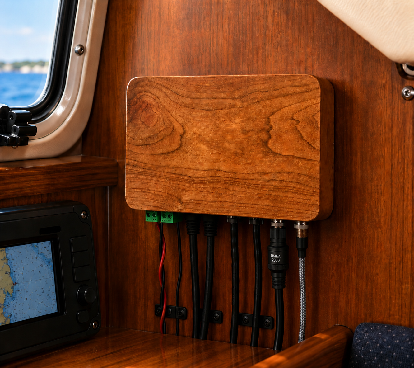
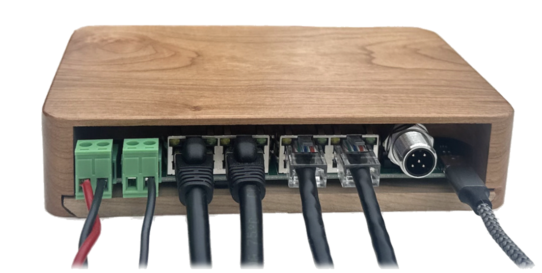
CAN, VE.Direct serial, WiFi (AP and client), Supabase cloud sync, secure OTA updates. Optionally pulls wind, GPS, heading, and other data from your boat network.
20-bit voltage and current resolution (TI INA228). Benchmarked against Victron. No second device required — use your existing shunt.
Digital alternator temperature sensor, Hall-effect alternator current sensor, 6-axis accelerometer + gyro, precision barometer.
No proprietary harnesses — splices into your existing wiring. WiFi
access-point mode for first-time setup with no boat network required.
Auto-discovery at alternator.local. USB-C programming.
Each regulator optionally contributes to a shared, anonymous dataset of real-world vessel performance, conditions, and energy use, going far beyond the alternator.
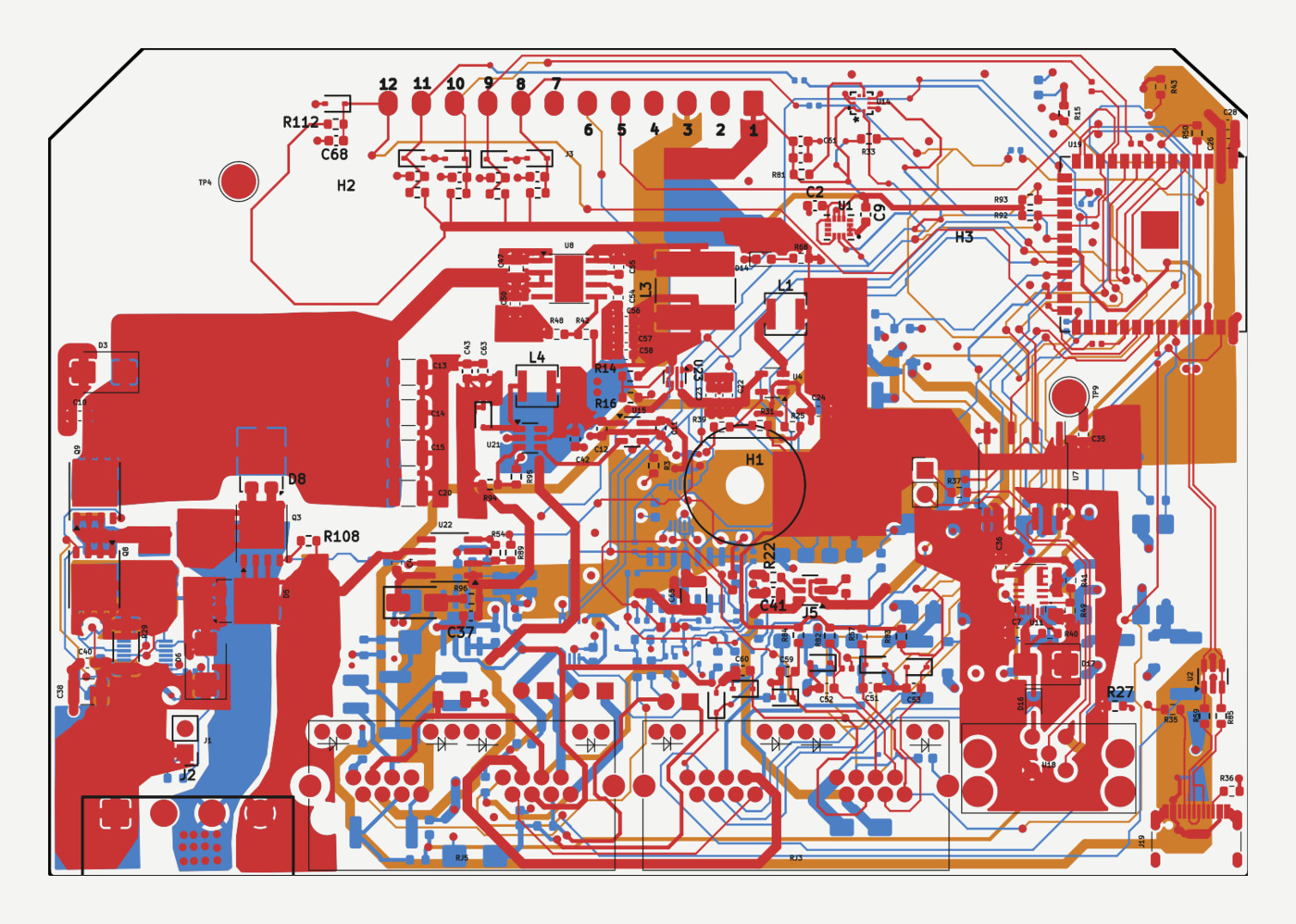
Hardware and software source.
Installation guide, engineering notes, technical deep dives.
What's in the box, and what else you'll need for a complete installation.