01
Basic Specs
12 / 24 / 36 / 48 V universal. P-type and N-type alternators. Three-stage charging with tail-current detection and re-bulk logic. Third-party BMS integration.
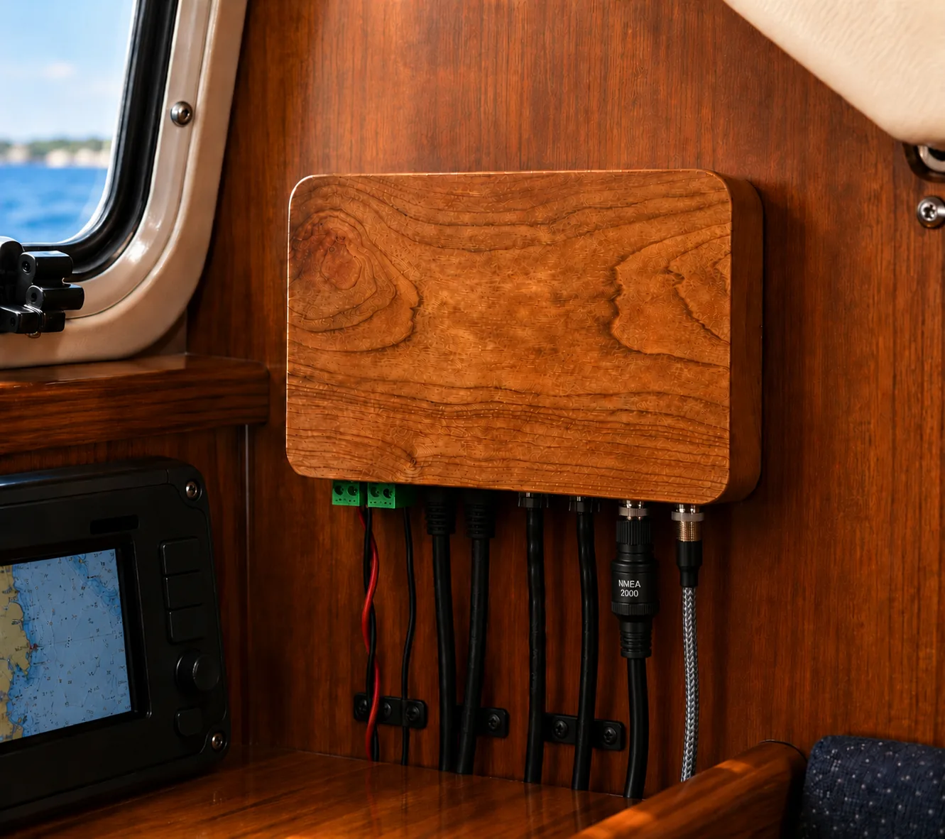

for use with Lithium Battery banks
 |  |  | 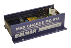 | 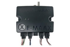 | |
| X Engineering XREG-010 | ARCO Zeus | Wakespeed WS500 Pro | Balmar MC-618-H | ElectroMaax E-Maax Pro X | |
|---|---|---|---|---|---|
| Price | |||||
| Complete, apples to apples | $452 | $890 | $1,050 | $455 | $539 |
| Advertised price, mismatched | $390 | $846 | $649 | $360 | $539The advertised price is the complete price. |
| Compatibility | |||||
| System voltages | 12, 24, 36, 48 V | 12, 24, 36, 48 VThe regulator itself runs on 12–30 V, so a 48 V bank cannot power it directly. | 12, 24, 48 V | 12 V | 12, 24 V |
| Alternator type | P, N | P, N | P, N | P only | P, N |
| Connectivity | Wi-FiAny browser, plus iOS and Android apps. | BluetoothiOS and Android apps. | BluetoothiOS and Android apps. | A magnet$442 of extra hardware adds a Bluetooth app connection. | Wi-FiNo app. Full settings access needs the Windows program over USB. |
| Native measurements | |||||
| Alternator current | Yes | Yes | Yes, or battery current, but not both | No | Yes |
| Battery current | Yes | Yes | Yes, or alternator current, but not both | No | Yes |
| Alternator temperature sensor | Digital | Thermistor | Thermistor | Thermistor | AnalogThe manual reads it as a voltage into the converter and never names the sensor type, possibly a thermistor. |
| Battery temperature sensor | Digital | Thermistor | Thermistor | Thermistor | AnalogThe manual reads it as a voltage into the converter and never names the sensor type, possibly a thermistor. |
| Protection | |||||
| Belt load manager | By amps, against engine RPM | By amps, against engine RPM | By amps, if the shunt is on the alternatorOtherwise open loop on field percentage. | By field percentageOpen loop, with no idea of engine RPM. | By field percentage, against engine RPM |
| Alternator temperature control | Holds a target temperature | Holds a target temperature | Holds a target temperature | Pulls the field back above a threshold | Half field above a thresholdFull cut over a limit.The product page says it holds a target, but manual’s settings list disagrees |
| Limp home mode | Yes | Removed in 2025 | Yes | No | No |
| Alternator health trend | Yes | No | No | No | No |
| Alternator lifetime prediction | Yes | No | No | No | No |
| Battery charging | |||||
| “Target zero battery current” mode | Yes | No | Yes | No | No |
| Act as independent battery monitor | Yes | State of charge onlyWith the shunt fitted. | No | No | No |
| Solar mode | Yes | No | No | No | No |
| Guided setup | Commissioning wizard | App wizard | Plug-n-Go | No | No |
| Integration | |||||
| NMEA 2000 | Send and receive | Send and receive | Send and receive | No | Send onlyPGN 127506, 127508, and 127751 go out. Nothing documented coming in. |
| Victron DVCC | In progress with VictronAugust 2026. | Yes | Yes | No | No |
| RV-C | Yes | Yes | Yes | No | No |
| The physical unit | |||||
| Dimensions | 6 × 4 × 1.3 in | 8.2 × 5.9 × 2.4 inWithout antenna. | 6.75 × 3.875 × 2.375 inFootprint 7.5 × 3.875 in over the mounting flanges. | 4.8 × 3.2 × 1.5 in | 6.0 × 5.0 in152 × 127 mm on the drawing. No depth figure is published. |
| Moisture ingress | No IP ratingConformally coated board. Extra potting possible by installer, not included. Connectors not waterproof, must use dielectric grease and mount above waterline. | IP66 case, IP67 connectors | Designed for IP67Diecast enclosure version. | No IP ratingEpoxy potted on an aluminum heat sink, probably good | IP56Withstands strong water jets |
| Accel and barometer on board | Yes | No | No | No | No |
| Data and updates | |||||
| Over-the-air updates | Yes | Yes | Yes | None published | No |
| Remote access from off the boat | Yes, through router | No | Yes, through a gateway | No | Yes, for the factoryThere is no owner-facing remote view. |
| Opt-in Cloud database | Yes, free | Advertised fall 2026 | No | No | No |
| Save, load, and share settings | Yes | Yes | Yes | No | Two custom profilesEdited in the Windows program. No settings file export or import is documented. |
| Logging on the device itself | About a month of history | None | None | A run-hours counter | None |
| Other | |||||
| Warranty | 2 years | 2 years | 2 years | 2 years | None found, published warranty excludes all products except alternators. |
| Source code published | YesGPLv3. | No | No | No | No |
| Schematics published | Yes | No | No | No | No |
12 / 24 / 36 / 48 V universal. P-type and N-type alternators. Three-stage charging with tail-current detection and re-bulk logic. Third-party BMS integration.
NMEA 2000 (CAN), Victron VE.Direct, Signal-K, WiFi, OTA updates.
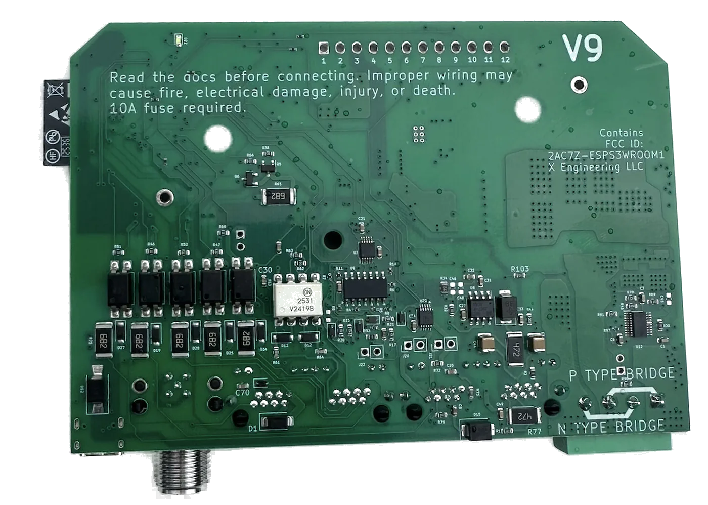
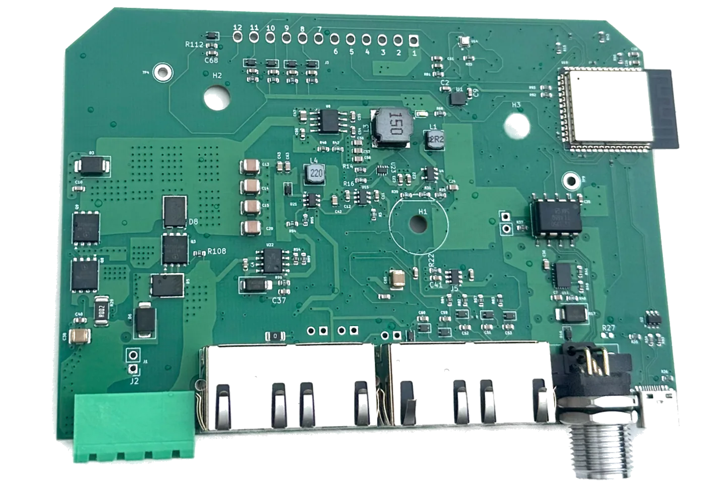
Digital alternator temperature sensor, Hall-effect alternator current sensor, 6-axis accelerometer + gyro, precision barometer.
Schematics, source code, design documentation — all published. No black boxes, no secrets.
Built in 20-bit voltage and current resolution (TI INA228). Benchmarked against BMV-712. No second device required — use any existing shunt.
A month of data stored locally; unlimited cloud history on top. Trend plots across years of cruising.
Multi-layer thermal, voltage, and current protections, with redundant hardware safety that stops output even if firmware fails. Conformal-coated, EMI-hardened, reverse-polarity-protected, and built for the marine environment.
Three cascaded PID loops with position-form PI, anti-windup, and bumpless transfer on every mode change. Smooth charging that won't spike, oscillate, or hunt.
Learns the alternator's output for a given RPM, field, voltage, and temperature, then flags deterioration. A physics-based life model predicts time-to-failure.
Compare live speed to your best polars for the wind and sea state: tune sail trim, spot a fouled bottom. An accelerometer computes a Motion Sickness Index plus anchorage and passage comfort scores.
Global leaderboards for distance, days at sea, alternator and solar output, speed by boat type, and more. Public fleet stats page.
Splices into your existing wiring / standard ethernet cables. Commissioning Wizard guides first setup, and full configurations can be imported/shared.
Long-form posts on alternator regulation, battery charging, and Open Business.

Opt in to the shared, anonymous fleet dataset: leaderboards, records and fleet-wide statistics.
See what it does →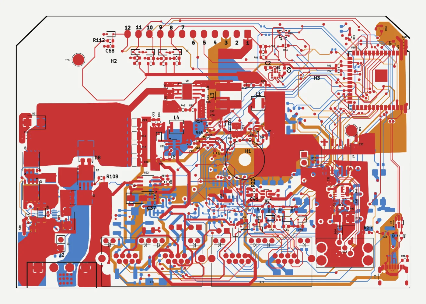
Software source.
Installation guide, engineering notes, and technical references.
What's in the box, and what else you'll need for a complete installation.
The regulator works with any alternator in a 12, 24, 36, or 48 V nominal system, P-type or N-type field excitation: in other words, 99% of them. An internally regulated alternator will first need to be converted to external regulation; that is a separate project, and there are many tutorials for it already.
Yes. While there are ways around this and you're free to do what you want, running two from one is discouraged.
Not for basic regulator operation. Extra features (over-the-air firmware updates, remote support and diagnostics, extended memory, configuration sharing, leaderboards, the solar forecast) do require an internet connection, commonly via the ship's network or a cell-phone hotspot.
Yes, as safe as possible for something charging a battery. If the ESP32 or its firmware fails completely, a pure-hardware overvoltage stage still prevents runaway alternator output. Before that, six software protection groups watch currents, voltages, temperatures, and fault on missing or out-of-range values.
A watchdog supervises the control loop. Every meaningful function is profiled and has visible timing. If the loop stalls, the processor reboots itself, and the cause is reported.
This product replaces the factory regulator and does not require a DC/DC charger. It allows any alternator to charge lithium (or any other chemistry) batteries directly, at programmable rates safe for the whole system.
The two can coexist: a DC/DC charger goes on doing its job for whatever source feeds it. What the regulator removes is the need to push alternator output through a converter rated well below the alternator's capability (typical marine units are 30–50 A) and to convert that energy a second time. Charge rate is then set by what the engine, belt, alternator, and battery can take, not by the converter in the middle.
The X Engineering regulator is open source: transparent and freely modifiable. It also has more functionality and costs less (likely due to no office, no dealer chain, no engineering team to pay for). X Engineering is possibly the first case of an AI-enabled company for a hardware product, at least in the marine industry, and it has greatly benefitted from Claude Code and free support / idea generation / peer review on internet forums. The downside? New product, not as proven as the incumbents.
Please do. The platform is built for owners who want to tweak and extend, especially now that AI coding tools make firmware customization realistic for motivated but non-expert owners. One recommendation: it is preferable to submit feature / pull requests first, and only fork the code as a last resort, to try to keep the future manageable for the fleet.
The documentation covers installation and setup step by step. For everything else there is the support forum, or email joe@xengineering.net.
Yes. An engine-speed limit table has ten editable breakpoints (100 to 4600 RPM by default), each one a ceiling in amps, or in kW if you would rather think in belt power. This can be used as a temperature limiter, but the regulator also separately includes closed-loop alternator temperature control. You set a limit and the regulator holds output just under it. It regulates against a 60-second projection of where temperature is heading rather than only where it is, so it eases off before the limit instead of overshooting and recovering. Above the limit sit two more tiers: a warning threshold that ramps the field to zero and starts a lockout, and a critical threshold that cuts the field immediately.
The gain over a fixed field percentage is that you keep full output while the alternator is still cold and give up output only when temperature demands it. If you prefer the conservative version, set the table low and let it be the only limit. The automatic temperature control works well where it has been tested, but every installation is a little different.
Yes, there are layered safeties which both warn you (external buzzer, notifications over CAN) and automatically reduce then cut the field to protect equipment.
Technically no. The regulator runs fine without one, but a battery shunt is highly recommended. What it adds is the fastest layer of system protection: it measures current thousands of times per second, so the regulator sees a sudden load disconnection (load dump) as a current step, often a much easier signal to detect than the resulting voltage rise, especially on larger banks.
Example: a 100 Ah bank, alternator delivering 100 A because the microwave and a water heater are running, and both switch off at once. Without a battery shunt, the first evidence is the voltage rising, and by then the full alternator output has already been diverted into a bank that may not want anywhere near that charge rate. With the shunt, the current step itself triggers the response, earlier and smoother. The shunt also enables battery-current-limited charging (holding a set charge current into the bank regardless of what the loads are doing), and gives you a highly accurate 20-bit battery monitor (state of charge) at no extra cost.
The shunt is recommended in all cases, but it is most essential with smaller banks and more delicate alternators.
Yes, for monitoring: the regulator listens for the bank's voltage, current, temperature, and state of charge on the NMEA 2000 network (Battery Status and DC Detailed Status PGNs, 127508/127506, on a user-selectable battery instance) and shows and logs them alongside its own measurements.
Protection and the fast control loop stay on the regulator's own wired sensors, always. Bus data arrives about once per second and lags reality by a second or two. That is fine for display and for the slow charge-limit coordination described below, and far too slow to catch a load dump, a sudden RPM change, or a BMS disconnect. Fast events need millisecond response, and that comes only from directly wired sensors.
The battery shunt is read by a 20-bit precision measurement chip (TI INA228), the same class of part used in laboratory power analyzers. Its dynamic range resolves milliamps of trickle current while still measuring hundreds of amps, and it samples fast enough to feed the protection layers described above, not just slow state-of-charge accounting. It tracks closely with the popular BMV-712.
The standard alternator-current sensor is a clamp-on Hall-effect sensor (±200 A / ±300 A / ±500 A ranges available; 300 A ships as the default). It installs in seconds: it clamps around the output cable, nothing is disconnected. In principle the regulator's precision shunt input can be repurposed to read an alternator-side shunt instead of a battery shunt, but that is a customization; the supported configuration is the Hall sensor on the alternator and the shunt (if fitted) on the battery. If your installation already has alternator-side shunts, get in touch for further discussion.
Yes. The regulator reads the alternator's stator signal (W-terminal) and converts it to engine RPM using your pulley ratio. That RPM drives the regulator's own RPM-indexed charge tables (the belt-load management), and it can optionally be broadcast onto NMEA 2000 as engine speed (PGN 127488) for your displays. Treat the absolute number as advisory (it is pulley-ratio math on an electrical frequency, not a calibrated tach), but it is exactly what belt-load logic needs. It works even at idle with the field off: all it needs is 25 mV on the low end, and it tolerates up to 100 V on the high end.
Three ring-lug digital temperature sensors (OneWire, sharing one cable) ship in the box in M4, M5, and M8 lug sizes, for the alternator, a battery terminal, and one more spot of your choosing. Battery temperature comes from that probe, or from NMEA 2000, VE.Direct, or RV-C battery data if the boat already publishes it. Charging is blocked below freezing to protect lithium banks, with a hot-battery lockout available as well; both need a battery reading, so fit the probe.
| Protocol | Speed | Who speaks it | X Regulator can receive | X Regulator can transmit |
|---|---|---|---|---|
| NMEA 2000 | 250 kbps | Most everything marine: chartplotters, MFDs, and GX devices |
|
|
| Victron VREG (proprietary) |
250 kbps | a GX device |
|
N/A |
| RV-C | 250 kbps | Lithionics-class BMS |
|
|
| BMS-Can | 500 kbps | Pylontech, BYD, JK, and REC | Not supported yet. Available by request. So is any other open BMS protocol. Note that there is only one CAN port, so you must choose a 500 kbps OR a 250 kbps system, not both. | N/A |
The first three can live on one wire at 250 kbps simultaneously. BMS-Can is the odd one out: different speed, different ID format, physically separate segment, cannot coexist, and is not common on boats, which favor NMEA 2000.
All CAN parameters are used for display and slow decision making. CAN is not fast or reliable enough for critical control loops.
On an MFD the regulator appears as a DC source you can add to any data page: the alternator's voltage, current and temperature on its own instance, the battery bank on another, charge stage, field drive percentage, and a dedicated temperature instance to alarm on. Engine RPM and the standard engine warning bits are available too, shipped off so they cannot collide with a real engine gateway.
A Victron GX reads it as a generic alternator. Victron documents that path in the Cerbo GX manual: a device that identifies as Electrical Generation / DC Generator and publishes DC type Alternator with voltage, current and temperature is displayed as an alternator without any Victron-side support for the specific product. The regulator meets every one of those requirements as shipped. Victron's own wording is that this data is used for display, not for system calculations, so the alternator shows up, but the GX does not fold it into DVCC current sharing.
Charge limits travel the other way and work today: with DVCC enabled, a GX broadcasts its charge voltage set-point to the whole bus, and the regulator follows it, clamped by its own protections, never raising a target. The charge current allocation a GX computes is different: it is addressed to one charger at a time, and goes only to charging devices a GX has built-in support for. That support does not exist for this regulator today; we are in touch with Victron about it.
Full page: NMEA 2000 in detail, including every instance number, what to change if something collides, and what is deliberately not sent.
Yes, that is the intended pattern. Set a temperature alarm on the regulator's temperature instance in your MFD. If the regulator's temperature sensor fails or goes stale, the regulator stops transmitting that PGN entirely rather than sending a stale number, which trips the "data lost" alarm every major MFD offers. A silently failed temperature sensor is how alternators cook; this closes that hole with the alarm infrastructure you already own.
Yes, today, with no extra configuration on the regulator: Signal K servers read the NMEA 2000 network, so everything in the table above flows into Signal K automatically, where you can set threshold alarms, push notifications to your phone, and build dashboards. A direct WiFi connection to Signal K (for boats with a Signal K server but no NMEA 2000 backbone) is a possible addition if someone requests it.
Three paths work right now:
You can. Cloud features are a single on/off switch in the interface. NMEA 2000 transmit ships off until you turn it on, message by message. Anything you don't enable does not run. With everything switched off it is a self-contained local device: web dashboard on the boat's network, no account, no internet.
The extra features exist because the marginal cost of adding them was negligible and the fleet data will allow interesting queries. Some examples: predicted passage and anchorage comfort based on data from similar boats in similar weather. Vessel performance comparisons (best <30-foot VMG upwind in 30 knots of wind with a motion sickness index under X). Alternator and battery lifetimes by manufacturer and use case. What should an alternator's temperature limit be, and how does it affect life? The list goes on once the database is built.
None of the above is allowed near the critical control path: the field control loop runs on its own ~30 ms cadence, and the slow work (writing logs to flash, uploading to the cloud) is deliberately deferred until the alternator field is off.
Since the firmware is open source, deleting what you don't like is always possible, but by switching it off instead you stay on the maintainable path, which is better for most users.
One thing, and only if you switch it on: Defer to Solar, which rests the alternator when the solar forecast says your panels will cover the next few days. It fetches from Open-Meteo, a public weather service, and that request carries your latitude and longitude. It doesn't go through xengineering servers, so the cloud switch doesn't govern it; it's a separate switch, and it ships off. With both off, nothing leaves the boat.
A 0–100 score for how comfortable an anchorage was, computed from the on-board 6-axis motion sensor. It measures how badly the boat rolls and pitches: heel weighted 65%, pitch 35%, full penalty at 12° of heel or 8° of pitch. It activates below 1.3 kt and is grayed out underway. Metrics are subject to change as the fleet gets calibrated.
Underway, the same sensor produces a passage comfort score and a motion sickness index instead.
Near the battery bank is preferred, within 3 to 6 ft where the layout allows: the regulator's ground wire carries field current, and a long run shifts the battery voltage reading. Distance from the engine is not a problem; see the next question.
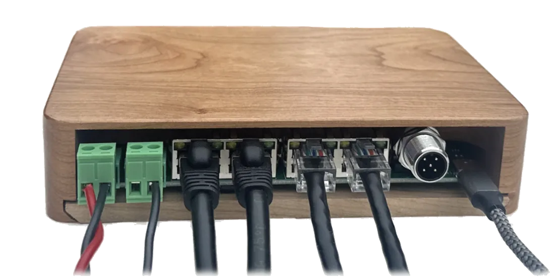
A bulkhead or wall is the preferred location. The enclosure is solid wood, so do not mount it directly to the engine. Look at where other wood is already living happily on the boat, and it will be fine in the same sort of place.
Above the waterline, and the higher the better, as with any electronics. The board is conformally coated and will resist splash, and with dielectric grease in the connectors it is about as weather-resistant as an electrical product gets short of full sealing.
No. At the recommended 14 AWG, a 6 m run drops about half a volt at worst-case field current, and the regulator compensates with a slightly higher field duty cycle. (Fields rarely run near 100% duty in any case; a field driven flat-out overheats the alternator long before wiring drop matters.)
Solid cherry hardwood, in two pieces: a wall dock that mounts to the bulkhead, and a base holding the board that slides down onto it on a 45° sliding dovetail. It is finished with Milesi XGC065. After trying a few other options, this one has the best moisture resistance.
The enclosure's full CAD (STEP, DXF, drawings) is published in the documentation. Print, machine, or build your own housing if you prefer. The box can be omitted from a shipment on request, but the price does not change: one product, one price, kept simple where possible.
No. The board's own consumption, measured at the DC input with the field off, is 0.7 W on a 12 V system and 1.31 W on a 48 V system; in the common idle state it drops to 0.27 W. The field is driven by a MOSFET with 7.2 mΩ on-resistance, so a typical 4–5 A field adds well under a quarter of a watt, and even a 15 A field (far above marine norms, and something the wiring won't handle) adds about 1.6 W spread into the board's copper.
Nothing here is even close to needing a heatsink, a fan, or clearance for airflow.
Within 2 business days of ordering unless otherwise noted.
Checkout takes United States addresses. For an order outside the US, email joe@xengineering.net before ordering.
30 days from receipt. You pay return shipping, and the unit must come back in as-new condition.
Two years, free replacement for any failure not caused by improper use.
for use with Lithium Battery banks
Each price with a dotted underline opens the full parts breakdown behind it.
Prices retrieved September 2026. Wakespeed and Balmar pricing from PKYS, ARCO from ARCO, X Engineering from X Engineering, ElectroMaax from ElectroMaax.
NMEA 2000 drop cable and miscellaneous wiring terminals and accessories are not included.
Data is obtained by best effort; no guarantee of correctness. Send corrections to joe@xengineering.net.
X Engineering XREG-010
Regulator unit$390
Wiring harnessnot supplied: two Cat5/Cat6 cables cut into four runs, plus your own power, ground, and field wire$39.90
Alternator temperature sensorin the box: three DS18B20 digital sensors supplied$0
Battery temperature sensorin the box: second sensor of the same three$0
Alternator current sensorin the box: QNHCK1-21 Hall clamp, 300 A$0
Battery shuntnot included: the boat’s existing, or a 500 A / 50 mV$22.10
Complete system$452
ARCO Zeus
Regulator unit$846
Wiring harnessesin the box: 14-pin Battery/Control and 7-pin Alternator, 6 ft each$0
Alternator temperature sensorin the box: ARCO thermistor, ARCO’s own curve only$0
Battery temperature sensorin the box: ARCO thermistor$0
Battery shuntnot included: needed for the battery current limit and state of charge$22.10
Alternator shuntnot included: a second shunt, needed for any alternator current reading$22.10
Complete system$890.20
Wakespeed WS500 Pro
Regulator unit$649
Wiring harnessordered separately, polarity-specific: P-type standard, 60 in$79.95
Alternator temperature sensornot included: the harness carries the plug only$29.95
Battery temperature sensornot included: kit WS500/BT-K, 10 ft$39.95
Battery shuntnot included: 500 A / 50 mV$22.10
Alternator current sensorno Wakespeed part exists: a third-party NMEA 2000 clamp, or move the single shunt to the alternator and lose battery current$229.05
Complete system$1,050
Balmar MC-618-H
Regulator unitharness included in the -H part number$359.75
Alternator temperature sensornot included: MC-TS-A, 54 in$42.34
Battery temperature sensornot included: MC-TS-B, 20 ft$52.98
Alternator current sensorno part exists. The MC-618 has no current input, so alternator current cannot be measured at any pricenone
Battery shuntno shunt input. A shunt can only be read by the separate SG200, which does not feed the regulatornone
Phone appnot in the regulator. SG200 kit plus Bluetooth gateway plus SmartLink cable is $442.17, left out of this totalnot counted
Complete system$455.07
ElectroMaax E-Maax Pro X
Regulator unitSMR-E-MAAX-PRO-X at ElectroMaax. A dealer lists the V7 part at $589$539
Wiring harnesssix-conductor power harness, same one for P and N type$0
Alternator temperature sensor$0
Battery temperature sensoron the battery voltage sense lead$0
Alternator current sensorsense lead and shunt both supplied$0
Battery shuntthe package lists the shunts$0
Complete system$539
For anything technical, the support forum is the better first stop.
For everything else (orders, shipping, anything the forum is not the place for):
joe@xengineering.net