The Modern Regulator — Automotive Lessons, Marine Control, and What Comes Next for Alternators
Marine and automotive alternators started with essentially the same machine: a wound rotor spinning inside a three-phase stator, with output controlled by varying current through the rotor field. Regulation, though, has diverged, and more recently, so has the machine. Automotive regulators have become tiny, highly optimized components within larger ECU-controlled systems, while marine regulators are still expected to manage battery decisions, alternator temperature, belt load, and often the entire charging strategy on their own. At the leading edge of the automotive industry, even the familiar six-diode alternator has evolved into a bidirectional starter-generator with active stator switching and controllable rotor excitation.
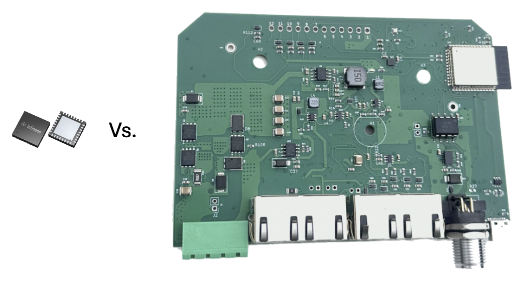
An automotive alternator regulator is not the overall charging authority. It is a local controller operating under the Engine Control Unit (ECU). The ECU supplies the voltage target, and the regulator varies field current to hold it. What sits with the ECU is the vehicle-level judgment: what that target ought to be, given battery state, engine load, and everything else happening in the car.
That division of labor works in automotive for reasons that don't hold in marine, and it's more about operating conditions than chemistry. A starter battery lives near full charge and is cycled shallowly, so its acceptance current is usually below what the alternator can safely produce. Modern AGM and EFB starter batteries can take substantial current, but they rarely need to.
Older systems hold a constant voltage or use basic temperature compensation. Newer “smart alternators” vary the voltage target according to engine load, battery state, accessory use and other conditions. But in all cases, the automotive regulator's controlled variable remains voltage.
A large lithium bank on a boat is a very different case. It deeply discharges, and often may accept more than everything the poor alternator can produce, and do it continuously, for hours. So a marine regulator has to answer extra questions:
- How much current can the alternator safely produce?
- How much can the belt transmit?
- How much load should be placed on the engine, and when?
- How much current can the battery safely accept at any given time, including BMS nuances?
- Which limit should control the machine right now?
Cars are standardized. Boats are customized.
Cars have another major difference: volume and consistency. A vehicle is built in huge numbers from known parts. The engineering team knows the alternator, battery, wiring, pulley ratio, engine, cooling environment and ECU. Development cycles are measured in years, and testing is extensive.
Boats are the inverse. There are hundreds of manufacturers and effectively endless combinations of engines, alternators, batteries, belt drives, wiring, and electrical equipment. Systems are assembled by generalists rather than engineered by specialists as complete systems. Then, over decades, they're modified by owners with varying goals and skill levels. Documentation is sparse, suppliers go out of business, and entropy accumulates. Testing is often little more than “it seems to be working”, until it doesn't, which is common enough.
Marine system voltages range from 12 to 48 V. Battery banks run from 50 Ah to a couple of orders of magnitude higher. Alternators, pulley ratios, battery chemistries, battery management systems and installation quality vary enormously. A useful marine regulator therefore has to work gracefully on a machine and electrical system its designer has never seen. Universality is by far the biggest development challenge.
What the automotive industry ships
Four representative regulator families define the category today: Infineon's TLE888x, STMicroelectronics' L9918, Bosch's CR665 (with the CR250 for 28 V commercial vehicles) and NXP's AR6000. They have converged on broadly the same architecture:
- a high-side field switch,
- LIN communication with the ECU,
- nonvolatile configuration programmed by the alternator manufacturer,
- alternator-speed measurement from a stator phase,
- field-current measurement,
- rate limiting,
- and thermal derating based on the regulator chip's own junction temperature.
LIN is a slow, inexpensive, single-wire polled bus using ordinary UART-style framing. Configuration is programmed during the alternator manufacturer's end-of-line process, and the memory implementations differ: Infineon's is rewritable EEPROM, rated for at least 100 program/erase cycles, NXP's AR6000 uses one-time-programmable fuses, and ST's L9918 permits at most sixteen writes. The Infineon TLE8881-2 is the worked example below because its datasheet was both available and thorough.
Line-by-line comparison
| Infineon TLE8881-2 | XREG-010 | |
|---|---|---|
| Role | ||
| What it is | A single chip inside the alternator. Closes its own voltage loop, normally on a target supplied by the engine computer. | A complete charge controller. Decides the target itself. |
| Needs a host computer | For smart-charging commands, yes. For basic regulation, no: it falls back to stored defaults. | No. |
| Field drive | ||
| Switch | Integrated high-side transistor on the chip. | External MOSFETs. |
| Alternator types | High-side (P) drive only. | P-type or N-type, selected by jumper. |
| Switch resistance | 60 mΩ typical at 25 °C; 95 mΩ hot. | 6.2 mΩ typical, 7.2 mΩ maximum. |
| Field current | Up to 12 A for the family. What it can report over LIN depends on the frame variant: 7.875 A, 10.2 A or 12.75 A. | 10 A, limited by the wiring connector choice rather than the switch. |
| Heat in the switch at 8 A | About 3.8 W cold, 6.1 W hot. | About 0.4 W. |
| Field switching frequency | 220 Hz fixed; 27 Hz during startup excitation. | 400 Hz default, adjustable from 100 Hz to 19.5 kHz. |
| Field resolution | 8-bit, 0.39% steps. | 12-bit, 0.024% steps. |
| What it measures | ||
| System voltage | On-chip divider. Guaranteed to ±200 mV between 10.5 and 16 V and ±700 mV above 16.5 V, across −40 to +150 °C. | Dedicated 20-bit monitor. 195 µV resolution, refreshed every 4.3 ms while the field is on, and mounted away from engine-level heat. |
| Voltage reported outward | 8-bit over an 8–24 V span: 100 mV steps, with every code from 161 upward reading 24 V. Filtered to 10, 5 or 1 Hz, or not reported at all. | Full resolution, streamed live. |
| Alternator output current | Not measured. | Measured by external Hall-effect sensor. |
| Battery current | Not measured. | Measured by external shunt. |
| Field current | Measured to ±250 mA up to 5 A. | Calculated, not measured. Planned for the next board revision. |
| Alternator temperature | Not measured. Only the chip's own die temperature, ±10 K. | Measured by external sensor on the alternator case. |
| Battery temperature | Not measured. | Not measured without a small wiring mod. Planned for the next board revision. |
| Engine speed | Stator-phase frequency divided by pole pairs. 500–25,500 rpm, ±10%. | Stator phase, calibrated against the vessel's own tachometer. |
| Control | ||
| What it regulates | System voltage, plus field-current limiting, speed-dependent current limiting and load-response control. Thermal derating responds to the chip's own die temperature, not alternator temperature. | System voltage, alternator current, battery current, and alternator temperature, whichever limit binds first. |
| System voltage range | 12 V. | 12, 24, 36 and 48 V systems. |
| Target step size | 25 mV, or 100 mV in two of its four message formats. | Not quantized to the 25/100 mV LIN steps; software resolution is much finer. |
| Held-voltage accuracy | ±200 mV on the regulated output, over the operating temperature range. Design-specified, not production-tested. | Not yet specified as a guaranteed system-level figure. Voltage ADC: 195 µV/LSB, ±0.05% maximum gain error before system-level effects. |
| Controller | Fixed PI. Four gain pairs are fixed in silicon; EEPROM selects which is used and at what speed. Engine speed, a LIN command and a voltage-error override can select among them. | Cascaded voltage-to-current-to-field control, with gains derived from a commissioning run on the machine. |
| Charge profile | None. Battery and vehicle-level charging decisions sit with the host computer. | Bulk, absorption, float and zero-current float; tail current, absorption timeout, rebulk and per-chemistry defaults. |
| Engine and belt | ||
| Rate-limits field increases | Yes. Full-scale ramp selectable from a fixed list between 0.28 and 15 s. Ignores steps below 3, 6.25 or 12%. Can disable the ramp above a programmed speed. | Yes. Current-setpoint rate limit plus a 0.15 V/s target ramp, both adjustable, with separate governors for wind-down and hunting. |
| Caps field current by speed | Yes. Two programmable levels on either side of a speed threshold fixed at 3400 rpm. | Charge-rate tables indexed by engine speed, plus a minimum-field floor learned at each speed on the actual alternator. |
| Caps alternator output current | No. | Yes, directly. |
| Protection | ||
| Overvoltage | Fixed cutoff at 16.5 V typical, with an analog backup at 17.4 V. Threshold can be lowered at low engine speed. | Multi-tier ladder referenced to the live target, a hardware overvoltage latch in the current monitor, and a hard field cut. |
| Over-temperature | Reduces the voltage target when the chip itself becomes hot, then shuts off the output. | Reduces alternator current against an alternator-temperature limit you set, with a warning ramp before any cut. |
| Fault reporting | Five LIN flags: hot, mechanical fault, electrical fault, communication error and communication timeout. | Full telemetry, event history, stored fault forensics and remote diagnostics. |
| Interfaces | ||
| Bus | LIN. One wire, single master, up to 19.2 kbit/s. | Wi-Fi with browser and phone app, NMEA 2000, RV-C, NMEA 0183 receive, and Victron charge-limit follow. |
| If communication is lost | Falls back to stored defaults; target glides at 0.2 V/s. | Falls back to local targets after an adjustable silence timeout, 30 s by default; target glides at 0.15 V/s. |
| Configuration | EEPROM, written in a factory mode requiring 32 V on the supply pin and the chip vendor's interface board. | Every setting changeable from a browser or phone, plus a guided commissioning procedure that measures the machine. |
| User interface | None. | Live plots, history, logging and alarms. |
| Physical | ||
| Package and rating | Five-pin power package, automotive qualified. Specified to +150 °C at the die; +175 °C absolute maximum. | Wood enclosure, mounted away from the alternator. |
| Standby current | Under 80 µA. | 20 mA at 12 V in the state it spends most of its life in: asleep, Wi-Fi still reachable. That is 0.27 W, or 0.48 Ah a day. 13 mA on a 24 V system, 8 mA on 48 V. About 50 mA at 12 V with the ignition on. Shutting the radio off entirely saves roughly 1 mA. Measured table. |
The Infineon figures are from the TLE8881-2 datasheet, revision 1.00.
Two rows are worth reading carefully. The Infineon ±200 mV is closed-loop accuracy on the regulated output across the operating temperature range, using only the chip's internal references. It is not a measurement-resolution limit, and 195 µV/LSB opposite it is resolution, not accuracy. The two are different quantities and neither substitutes for the other. Standby current is not like-for-like either: 80 µA is one chip in a parked car, against a complete instrument that stays awake, keeps measuring and stays reachable.
What can be changed?
An automotive regulator may contain many configurable parameters, but that does not mean the vehicle can change them at will. Most are programmed once by the alternator manufacturer before the alternator is assembled. For the TLE8881-2, the chip vendor sells an interface board specifically for this purpose. Programming mode requires at least 32 V on the supply pin, a voltage that cannot occur in a normally operating 12 V vehicle. That is deliberate: accidental reprogramming in service becomes effectively impossible. It is not an obstacle to driving the chip at runtime, though. An Arduino and a LIN transceiver could command the runtime parameters perfectly well. The 32 V hurdle applies only to rewriting the nonvolatile factory configuration.
The list of things that can be changed while the engine is running (via LIN) is short:
- voltage target,
- ramp time,
- speed above which the ramp is disabled,
- field-current limit,
- a temperature-threshold offset,
- and which of four stored controller gain sets is active.
Everything else is frozen, including the gains themselves, the overvoltage threshold, pole-pair count and startup-excitation level. Four gain sets selected according to engine speed are a good solution for a chip designed to live inside one particular alternator model in a known vehicle. They are a bad solution for a regulator expected to work on a machine it has never seen.
The machine replacing the alternator
At the high end of the automotive market, the conventional alternator is gradually being replaced by the 48 V belt starter-generator, or BSG. A BSG runs in both directions, which is what separates it from an alternator. During normal driving and braking, power flows from the engine through the belt into the BSG and on to the battery. During engine restart or torque assist it flows the other way, from the battery through the BSG and the belt into the engine. That lets one belt-driven machine replace the alternator, restart the engine at traffic lights, add engine torque during acceleration and recover energy during deceleration. The conventional pinion starter often remains anyway, particularly for cold starts where the required torque can exceed what the accessory belt can transmit reliably.
Valeo's iBSG is a useful example. Valeo describes it as a synchronous claw-pole machine, with up to 15 kW of peak regenerative braking, 10 kW of peak mechanical power and maximum efficiency above 85%. The company says the product has roughly 40% worldwide market share and production above 1.5 million units per year.
The wound rotor didn't disappear
This transition is usually described as the wound-field alternator giving way to permanent-magnet or induction motors. That did not happen universally. Valeo's claw-pole starter-generator architecture retains a wound rotor. Published work on Valeo mild-hybrid claw-pole machines shows a rotor whose principal excitation comes from DC current in the rotor winding, with small permanent magnets between the claw teeth reducing leakage and saturation rather than providing the primary field; Valeo's own starter-alternator material shows the familiar claw rotor, rotor bobbin, brushes and slip rings. That describes the machine class. Whether every one of those details holds for the current iBSG generation is not something the public sources settle.
That makes the machine very familiar. A conventional alternator is a DC field, a wound claw-pole rotor, a three-phase stator and a diode rectifier. The wound-field BSG is a controlled DC field, the same wound claw-pole rotor, a three-phase stator and a bidirectional MOSFET bridge. The rotor is still magnetized electrically. What changes most dramatically is what happens on the stator side.
Diodes → switches
A conventional alternator feeds its three stator phases through a six-diode rectifier. The diodes decide when each phase conducts. The regulator has no direct switching control over the stator currents. It moves the rotor field and the stator currents follow.
A BSG replaces that passive rectifier with a three-phase inverter, six actively controlled switch positions. In generating mode, the bridge takes AC power from the stator and sends it into the DC bus. In motor mode, the same hardware does the opposite: it takes DC power from the battery and synthesizes controlled three-phase currents in the stator. That means the controller can determine torque and power flow directly instead of controlling them only indirectly through the field. The machine now has two electromagnetic control inputs:
- stator current, controlled rapidly by the three-phase bridge;
- rotor excitation, controlled separately through the field winding.
Why put a full bridge on a DC field?
The field winding still needs power electronics of its own. A conventional alternator regulator (like the XREG-010) needs only a single field switch and a flyback path. Turn the switch on and current builds in the inductive rotor winding. Turn it off and the stored magnetic energy keeps the current circulating until it decays through the winding's resistance and inductance, which takes 100 ms or so. That is simple and robust, but it means the regulator can build field much more aggressively than it can remove it.
A full H-bridge around the field winding changes that by applying positive voltage to build field, approximately zero volts to recirculate or maintain it, or negative voltage to force the existing field current toward zero. For a field winding, V = L(di/dt) + Ri. With a substantial reverse voltage applied, di/dt becomes much more negative, and the magnetic field can collapse faster.
The purpose is not primarily to reverse the magnetic polarity of the rotor. Changing between generating and motoring torque is handled by the phase relationship of the stator currents. The useful trick is fast demagnetization, which matters during a fault. A generator will continue producing voltage even after the electrical system no longer wants the power. Automotive 48 V system literature specifically identifies rapid de-energization and demagnetization of a DC-excited rotor as a way to prevent dangerous DC-link overvoltage during faults. A wound-field machine has an electrical OFF switch for its excitation.
A full field bridge makes less sense for an aftermarket alternator regulator
That same full-bridge idea is less attractive for a universal marine regulator. A true H-bridge needs electrical access to both ends of the field winding, and many conventional alternators do not provide that externally. One brush is internally connected to B+ or ground, depending on the alternator type. Using a full bridge would therefore require owners to modify or replace the brush assembly so that both brushes were isolated and brought outside the alternator.
The benefit itself is not small. A published 48 V belt-starter-generator design says outright that the full H-bridge is there for rapid rotor demagnetization during load dump and overvoltage faults, and TI describes the same class of machine as a three-phase stator inverter, a DC-excited rotor fed through brushes and slip rings, and a full H-bridge for the rotor excitation. So this is a potentially large improvement in field-decay speed, but a narrow benefit relative to the installation complexity of isolating both brushes on every alternator the regulator might meet.
A half-bridge doesn't solve the underlying problem either. If the other end of the field winding remains permanently attached to B+ or ground, a half-bridge cannot freely apply reverse voltage across the winding. Fortunately, neither is necessary just to get faster field collapse.
Faster demagnetization without touching the brushes
A good alternative, possibly for future X Engineering designs, is to change the flyback circuit. The conventional flyback diode deliberately keeps the voltage across an inductive load very small when the switch opens. That protects the transistor, but the low reverse voltage also makes current decay slowly.
A higher-voltage clamp does the opposite. When the field switch turns off, the switched end of the winding is allowed to move beyond the normal supply rail until a controlled clamp voltage is reached. The field then sees a much larger voltage opposing its existing current, and the greater that opposing voltage, the faster the field current falls. This is a standard technique for inductive loads. TI describes the distinction directly: ordinary freewheeling produces slow current decay, while clamping the turn-off voltage much higher produces rapid demagnetization. ST describes the same approach in automotive drivers as fast demagnetization or fast current decay.
That means a future marine regulator could gain much of the useful part of an H-bridge, substantially faster loss of field during an overvoltage event, BMS charge-stop command or sudden load rejection, without requiring any modification to the alternator's brushes. The trade is voltage stress and heat. The magnetic energy stored in the rotor, E = ½LI2, still has to go somewhere. A conventional flyback diode dissipates it slowly. A high-voltage clamp dissipates it much faster, so the switching device, TVS or other clamp hardware has to survive that pulse energy. That is a much more practical problem to solve inside the regulator than asking every owner to rebuild a brush holder.
The real efficiency step is on the stator, not the rotor
Changing the field flyback path improves response and protection, but it does almost nothing for alternator efficiency. The rotor still requires essentially the same field current, and its dominant loss remains Pfield = If2Rf.
The more interesting efficiency opportunity is replacing the six stator diodes. At high current, diode losses become significant because two rectifier devices are in the current path at any moment. As a rough approximation, Pdiodes ≈ 2VfI. At 100 A and a 0.9 V forward drop, that is approximately 2 × 0.9 × 100 = 180 W, and at 200 A it becomes roughly 360 W. That is heat produced purely by rectification. MOSFETs replace the roughly fixed diode voltage drop with resistive loss, P ≈ I2R, and with sufficiently low resistance that can be dramatically smaller.
Synchronous rectification
The first step does not need to turn the alternator into a motor drive. The six MOSFETs can simply reproduce the switching behavior of the original six diodes: whenever a diode would naturally conduct, its corresponding MOSFET is turned on. That is called synchronous rectification.
A published automotive Lundell-alternator experiment did exactly this. At 1 kW electrical output and 2000 rpm, rectifier losses fell from 152 W to 32 W, close to a 75% reduction. One caveat on that measurement: the passive case used the MOSFETs' own body diodes rather than a production six-diode bridge. The authors argue the result carries over to conventional automotive diode rectifiers.
That does not mean total alternator efficiency suddenly improves by ten percentage points. Stator copper loss, rotor copper loss, magnetic loss, bearings, brushes and fan power remain. But at 12 V, where hundreds of amps are common and diode voltage drop is a substantial fraction of system voltage, several absolute percentage points of mechanical-to-electrical efficiency are plausible. It also means less heat inside the alternator for the same electrical output, or more usable electrical output at the same thermal limit. The benefit becomes progressively smaller as system voltage rises because the roughly fixed diode drop represents a smaller fraction of the power being transferred.
Another possibility
Once the six stator diodes have become six controlled switch positions, another path opens. They do not have to imitate diodes. A fully active bridge can intentionally control the stator phase currents. The machine can then regulate torque and electrical power directly and much faster than it can by waiting for the rotor field to change. At that point the machine has two control axes: the rotor field, which is slow, and the stator current, which is fast. The same six-switch hardware can potentially support:
- synchronous rectification,
- active current regulation,
- torque regulation,
- improved low-speed operation,
- controlled bidirectional power flow,
- and eventually motor operation.
This is a much larger software and sensing problem than synchronous rectification. The published Lundell work explicitly notes that simple synchronous rectification avoids the current sensing, rotor-position information and advanced control loops required by a fully active rectifier. So there is a fairly natural progression, and it can happen without abandoning the wound-field machine:
- Conventional alternator. Rotor: single field switch and flyback. Stator: six diodes.
- Improved field control. Rotor: single field switch and a high-voltage demagnetization clamp. Stator: six diodes. The alternator remains completely conventional internally, but field current can collapse much faster.
- Synchronous rectification. Rotor: improved field control. Stator: six controlled MOSFET switch positions operating like idealized diodes. Now rectifier losses fall substantially.
- Fully active machine. Rotor: controlled field. Stator: six-switch PWM bridge with active phase-current control. At that point the electronics begin to look much more like those of a belt starter-generator than a conventional alternator regulator.
Why wound-field machines survived into the hybrid era
Permanent-magnet machines have obvious attractions. They eliminate brushes, slip rings, rotor copper loss and the field power electronics. But a wound rotor buys something valuable: controllable magnetic flux. At low speed, excitation can be increased to produce more torque. At high speed, excitation can be reduced to limit generated voltage. During generation, field strength can be optimized for the operating point. And during a serious electrical fault, the rotor can be demagnetized.
That last capability matters for a machine mechanically attached to an engine. The electronics may stop asking for power, but the engine can continue forcing the rotor to spin. A permanent-magnet rotor keeps producing magnetic flux regardless. A wound-field rotor can be told to stop. That helps explain why the same basic claw-pole rotor used by alternators has survived into some sophisticated hybrid machines.
Full electric vehicles remove it
Battery-electric vehicles skip the issue entirely. The traction battery already contains a large electrical energy source, so a DC-DC converter supplies the low-voltage electrical system and there is no alternator at all.
Boats will be using alternators for a long time
None of this automotive transition is likely to reach boats quickly. Belt starter-generator production remains in the low single-digit millions. Valeo says it makes more than 1.5 million units a year at roughly 40% worldwide market share; if both figures refer to the same denominator (an inference, not a published number), that implies a market around 3.75 million units annually. Global motor-vehicle production was 96.4 million in 2025.
Boats also keep engines in service for decades. Wound-field alternators are therefore likely to remain standard marine equipment well past the point when cars have largely stopped fitting conventional ones.
But the automotive transition helps explain why conventional alternator-regulator technology now reads as mature rather than fast-moving. It has not stopped (Bosch's current CR665 carries an active freewheeling MOSFET and active overvoltage handling), but much of the industry's engineering effort moved, sensibly, toward inverters, starter-generators, and electrified drivetrains years ago.
Different problems
Automotive charging hardware sets a useful engineering benchmark. These chips and machines are produced in enormous volumes, qualified for harsh environments and developed by organizations with engineering resources far beyond those available in the marine charging industry. But they are solving a different problem.
The automotive regulator is optimized for one known alternator installed in one known electrical system under the supervision of another computer. A marine regulator has to walk onto an unknown boat, connected to an unknown alternator, battery, engine, belt drive and collection of other controllers, and figure out how to operate all of it safely. Future blog posts will expand on how X Engineering does that.
Further reading: for how this all started (the cutout relay, the vibrating-contact regulator, and the long road to a solid-state one), there is a first-hand account at the IEEE Engineering and Technology History Wiki: The Story of the Automobile Voltage Regulator.