These inputs can only differentiate between a “low” signal (0V) and a “high” signal (3.3V or 5V). There is some tolerance to these values, depends on the microcontroller. For example, 3.2V is going to be considered “high” and 0.2V will be “low”. Low is also known as 0 or “false” and high is also known as 1, or “true”.
A digital input pin can “float” between a high and a low value, if not forced one way or the other.
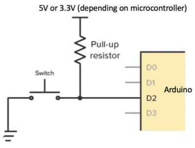
A Pull Up resistor makes a connection between a 5V (or 3.3V) power source and said digital input pin, so that it is pulled up (until something else, like a switch, grounds it out.)
A Pull Down resistor makes a connection between said pin and ground, to pull it down to ground unless a switch pulls it up.
The purpose of the resistor is to limit current, so that the switch is still able to overcome the influence of the resistor. In the image below, if the Pull-up resistor was replaced with a direct jumper, when the switch was closed, the power supply would have a direct path to ground, obviously not good. A resistance of 10k to 100kΩ generally works.
In place of the manual switch shown above, many times this same circuit is used with a sensor that acts like a switch, opening and closing continuity as a function of some input. Useful examples are oil pressure switches, coolant temperature switches, and proximity probes.
Since these circuits are so common, Arduino’s come with internal pull up resistors (value between 20k and 50k).
To enable internal pull-ups on an Arduino, use this type of code in the setup() function:
pinMode(5, INPUT_PULLUP);
instead of
pinMode(5, INPUT);
Easy and so useful!
Protecting Inputs
The digital inputs are sensitive, they only accept specific voltages and can be damaged by voltage spikes. A voltage spike can be really quick, microseconds, and caused by something innocuous like having long wires leading to a switch. To overcome both of these problems, it’s good practice to use optical isolation. An optical isolator goes between the switch and the digital input pins, acting something like a relay. A high voltage fed to the input side of this “relay” (from your switch) creates a light signal. That light signal closes a switch on the output side, and the output side is routed to the microcontrollers digital input pin.
An example is LTV247
Here is a good guide to specifying the correct optical isolator and here for selecting the input and output resistors.
My own additional comments:
- All optical isolators will have a huge isolation capability (blocking of high voltages), so unless the application is special, this is not a big concern.
- Speed is always “fast”, so ditto on that spec.
- Forward Current refers to current flowing into the input side of the optocoupler. You’ll usually know the voltage range of the input circuit. In the case of a manual toggle switch, it’s whatever voltage you feed the switch, usually 12V in an automotive/marine application. For LTV247, the maximum allowable forward current is 50mA, and I want to accept a switched signal up to 17V. Therefore, the current limiting resistor should be at least 350 ohms (solved for this using Ohm’s law). A higher value is better (= longer life for the isolator), but going too high will fail to produce the LED voltage drop across it of 1.2 (Vf). For the sake of the example design, I have chosen 1000 Ohms.
- Current transfer ratio: Multiply the current on the input side by the CTR to get the maximum possible current on the output side. CTR for LTV247 is 0.5 (worst case, lowest value on datasheet).
- A resistor on the output side should be sized so that the output current (calculated from CTR) at the microcontroller’s logic level voltage (3.3V in this case) is enough to pull the signal “low”.
–