I2c and SPI are wonders of the world, they’re so useful.
Using just 2 wires (i2c) or 4 wires (SPI), these communication standards allow easy connection between specialized IC’s and the Arduino itself, with basically zero programming.
Taking i2c as and example, large numbers of IC’s can run off of the same two wires, which are called SDA and SCL. Here they’re the orange and green:
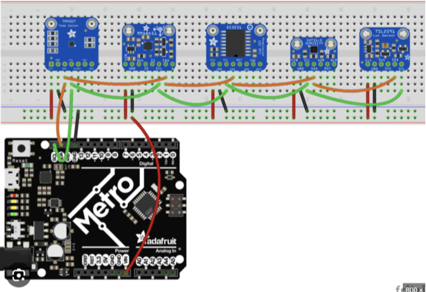
Some UNO boards will have their own dedicated i2c ports, and others they’re shared with A4 and A5, meaning if you want to use i2c, you lose two Analog Inputs.
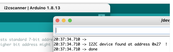
Since there are so many devices on the same “bus” wires, they’re identified digitally by specific addresses, and these are referenced in the code to operate them. If the address of a specific component is not known, this is a handy code to read it. Find it in the Arduino Library Manager, easier to install all libraries through there than downloading and trying to place them in the correct folder.
Note: This communication bus uses pull up resistors that are usually pre- integrated into the accessory boards, so no need to worry about them. However, if working directly with an i2c chip, or using a huge number of boards/chips at once, it’s something you should google.
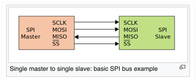
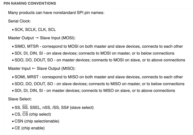
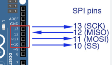
SPI is pretty much the same as i2c but with 4 wires instead of 2. The naming can get inconsistent between manufacturers, so use these images to make connections:
Multiple devices can be chained together on the same bus, similar to i2c.
Pin numbers on Arduino are:
Another important note: these protocols were developed for communication in small spaces, and wire length is not supposed to be very long. Some say 50cm limit. I have found this overly conservative, but don’t expect it to work 5m away. In some cases it may, depending on the speed and amount of data being transmitted, but those are more advanced topics that I haven’t had a need to study in detail yet.